Friday, December 25, 2009

Case Studies of Wind Hydrogen System (part 2)

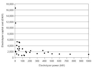
During 2004 and 2005, four major wind-hydrogen projects have been launched in Europe: the Utsira project in Norway; the HARI project at Loughborough; the promoting unst renewable energy project in Unst, UK; and the RES2H2 project in Greece and Spain.

On the Utsira Island, a wind-hydrogen system was installed to serve 10 households with a peak demand of 45 kW in an autonomous mode. The existing grid connection was kept for emergency situations to avoid the high costs of redundancy. The hydrogen plant consists of a 48 kW alkaline electrolyzer producing 10 Nm3/h H2, a hydrogen compressor for the filling of a 12 m3 storage tank at 200 bars with a 2400 Nm3 H2 capacity, a hydrogen generation set of 55 kW, and a PEM fuel cell of 10 kW nominal power. A 600 kW wind turbine supplies a varying portion of its power to the system feeding the rest of its power to the grid. At maximum load, the electrolyzer and compressor need approximately 54 kW of electrical power.

In the “PURE” project on the Shetland Islands, the wind-hydrogen system is composed of two wind generators of 15 kW power each, a 15 kW advanced alkaline electrolyzer operating
at 55 bars, a 16-cylinder stack of 44 Nm3 H2 capacity at the same pressure, and a 5 kW PEM fuel cell.

A hydrogen plant was integrated to an existing infrastructure of renewables, which included two 25 kW wind turbines, photovoltaics, and two microhydroelectric turbines in the HARI project. The wind turbines are two-bladed, stall-regulated, and pitch overspeed. The hydrogen plant is composed of a 36 kW alkaline electrolyzer, a hydrogen compressor, 48 pressurized hydrogen cylinders of 2856 Nm3 capacity at 13.7 MPa, and two
different fuel cells of 2 and 5 kW nominal power.

The alkaline electrolyzer with a 46-cell stack produces 8 Nm3/h H2 at 2.5 MPa and operates in a 20–100% range of its nominal power. The 3.75 kW single-stage hydrogen compressor has a capacity of 11 Nm3/h for an inlet pressure of 2.5 MPa and an 8:1 compression rate. To reduce the on/off switching cycles of the electrolyzer, which affect its long-term stability and performance, a 20 kWh battery was incorporated. The battery helped to moderate the power supply variations to the electrolyzer.

The mean electrolyzer stack efficiency measured was 75%, whereas the average conversion efficiency of the electrolyzer–battery–compressor system was 49%, including the balance of plant losses. The performance of the electrolyzer decreased gradually over 2 years of operation, with the stack power requirement increasing from 36 to 39 kW and the total power requirement, including the hydrogen purification section and auxiliaries, from a maximum of 43 to 45 kW.

In the frame of the RES2H2 project, a wind-hydrogen system was installed and tested in a wind park near Athens, Greece. The hydrogen system consists of a 25 kW alkaline electrolyzer
producing 5 Nm3/h H2, a hydrogen compressor for filling high-pressure cylinders at 220 bars and metal hydride tanks. The plant and all the auxiliaries are connected to a 500 kW wind turbine, which feeds the rest of its power to the grid. Under variable power input, the electrolyzer rarely reaches its nominal operating temperature of 80°C, and its efficiency varies from 70% to 85% for an electrolysis temperature in the range 45–70°C.

source: (2009) Hydrogen Fuel, Production, Storage & Transportation by Ram B Gupta (ed)

Monday, December 21, 2009

Case Studies of Wind Hydrogen System (part 1)

Water electrolyzers have been designed in the past for continuous or discontinuous operation with grid current converted to DC current. Most of the case studies reported in the literature refer to stand-alone systems. In fact, several of these stand-alone systems have part of their auxiliaries connected to the grid, or use the electrical grid as backup power.

A wind-hydrogen system of 20 kW installed power has been developed, constructed, and optimized at the Fachhochschule Wiesbaden in Germany since 1985. A 20 kW wind energy converter, designed for stand-alone operation, feeds DC to a pressurized alkaline electrolyzer of 20 kW, and the produced hydrogen is used in two gas motor generators of 8 and 4 kW electrical output. The overall energy effi ciency from wind electricity to gas generator electricity is around 15%.

At the University of Stralsund in Germany, a 100 kW wind turbine and a 20 kW alkaline electrolyzer supplying hydrogen at 25 bars to a storage tank of 8 m3 have been in operation for several years. According to the wind speed, the asynchronous wind generator can be operated at 1000 or 1500 rpm producing 20 or 100 kW of electricity, respectively. Both the static and the dynamic behaviors of the wind-hydrogen system were investigated, and an electrolyzer efficiency of approximately 65% with respect to the HHV has been reported.

The Hydrogen Research Institute in Canada has developed and tested a stand-alone renewable energy system composed of a 10 kW wind turbine, a 1 kWpeak photovoltaic array, a 5 kW alkaline electrolyzer, and a 5 kW PEM fuel cell. The components of the system are electrically integrated on a 48 V DC bus.

A small stand-alone, wind-powered hydrogen production plant was designed, constructed, and tested in Italy, at the National Agency for New Technologies, Energy and the Environment. The main aim of the project was to study the control of a wind turbine to produce a smooth power output, the tolerance of an electrolyzer to fluctuating power inputs, and the overall economics of a wind-hydrogen system.

The system was composed of a 5.2 kW wind turbine with a synchronous generator at variable speed, a 2.25 kW electrolyzer, and a 330 Ah battery bank. The variable frequency AC power output from the turbine was rectified and supplied to the electrolyzer. Hydrogen purity remained satisfactory even at low-capacity factors, with oxygen content in hydrogen in the range 0.15–0.35 vol%, although the efficiency of the electrolyzer stack (50%) was lower than state-of-the-art electrolyzers (70%).

Friday, December 18, 2009

Sizing of the Electrolyzer in Wind Hydrogen System

For a given wind power installed, the sizing of the electrolyzer is not trivial. In the case of “stand-alone” systems, a one-to-one approach is often proposed, with the electrolyzer power input being equal to the nominal power output of the wind turbine. In this way, the electrolyzer should be able to retrieve all the wind power in the absence of load. In gridconnected systems, the same approach leads to the choice of an electrolyzer with a power supply equal to the power output of the wind turbine minus a “base load.”

However, the specific capital cost of the electrolyzer being almost equal to the cost of a wind turbine, it is important to take into account the capacity factor of the electrolyzer that will always be smaller than that of the wind turbine.

Electrolyzers are generally current-controlled, which means that a certain DC is imposed according to the desired hydrogen production. In a wind-hydrogen system, the wind turbine
power available for the operation of the electrolyzer is generally known; therefore, the power input should be transformed to a current input.

The voltage–current relation of an electrolyzer is not very simple because it depends on the temperature, pressure, and other construction characteristics. For a given electrolyzer, it is possible to experimentally establish the I–V curve at different temperatures and pressures, and deduce a temperature-dependent current–power curve.

The sizing of the wind turbine, electrolyzer, and auxiliaries is greatly affected by whether the wind-hydrogen system is grid connected or stand alone. The cells can be made in any size, and any number of cells can be stacked in a series depending on the desired output and design point selected. The design point, namely the current density for the cell, is case sensitive and depends on whether the system is operational cost critical or capital cost critical. The cell voltage and therefore the specific power consumption of the electrolyzer depend on the current density according to a I–V curve.

If the capital cost is more important than the operating cost, which depends on electricity price, the optimum current density should be shifted toward the higher range with a lower efficiency. If the operating cost is more significant than the cost of money, the current density should be shifted toward the lower range, or expensive activated electrodes may be used to increase the efficiency. Module material costs usually represent between 44% and 56% of the total material costs in wind-hydrogen system.

Commercial water electrolyzers cover a wide range of hydrogen production rates from 0.001 to 750 Nm3/h. Small hydrogen generators are intended for laboratory use, where hydrogen is often used as a carrier in analytical instruments, whereas large units are used in different fields of the chemical industry.


The actual capital cost of different electrolyzers operating at pressures between atmospheric pressure and 30 bars is presented in Figure above based on offers from manufacturers. There is a wide variation in the specific capital cost of small-size electrolyzers due to the different technical characteristics and options included. The specific capital cost of very small laboratory electrolyzers may exceed 30,000 €/kW, but has not been shown here for simplicity.

There are no large variations in the specific cost of medium-to-large-size electrolyzers, that is, above 200 kW, mainly because there are very few manufacturers around the world that are actually supplying equipment of such a size. The manufacturing process of electrolyzers in wind-hydrogen system is still intensely manual and the prices shown here refer to individual items without taking into account any volume effect.

The specific capital cost of very small laboratory electrolyzers, producing <>

Generally, in wind-hydrogen system the electrolyzer cost increases with hydrogen purity and delivery pressure. In fact, a purification section for the removal of oxygen and the reduction of humidity to a concentration below 10 ppm may represent 30–40% of the total cost.

Advanced electrolyzers actually supply hydrogen at pressures up to 30 bars and there are prototypes with a delivery pressure of up to 100 bars. They are more expensive than atmospheric electrolyzers, but their use decreases the cost of storage: hydrogen may be directly stored at the delivery pressure, and if a compressor is used for filling high-pressure cylinders, it only needs one stage instead of three or four.

source: (2009) Hydrogen Fuel, Production, Storage & Transportation by Ram B Gupta (ed)

Tuesday, December 15, 2009

History of Wind-Hydrogen System

During the development of electrical generating equipment in the late 1800s, both Europe and America began to experiment with wind power for electrical generation. Among the first to develop wind-powered electrical generators was the Danish professor, Poul La Cour, who worked on wind systems from 1891 to 1908. He also saw the use of hydrogen as a fuel and the use of wind-powered electrical generators to electrolyze hydrogen
and oxygen from water (wind-hydrogen system).

Another early investigator who promoted wind-powered hydrogen production systems was J.B.S. Haldane a British biochemist at Cambridge, England. In 1923, he predicted that England’s energy problems could be solved with a large number of wind generators supplying high voltage power for hydrogen production.

During World War II, Vannovar Bush was the Director of the U.S. Wartime Office of Scientific Research and Development. He was concerned about American fuel reserves and thought that wind generators could be a solution. Percy Thomas was a wind power advocate on the Federal Power Commission, who convinced the Department of the Interior to construct a large prototype wind generator.

In 1951, the House Committee on Interior and Insular Affairs killed this plan. Wind-generated electricity could not compete with coal that was selling for $2.50 per ton or diesel fuel at $0.10 per gallon. The promise of even less expensive electricity that was too cheap to meter from nuclear power plants resulted in the loss of almost all Federal programs to develop wind-powered energy systems.

Wednesday, November 25, 2009

Disadvantages of Hydrogen Fuel Cells

Hydrogen fuel cells are the wave of the future. At least that is what many would want you to believe. They have a point because a hydrogen fuel cell is a novel way to power a car. The car would require no gasoline, run on hydrogen and its only waste would be water, a natural and safe emission. However, it is not a perfect science by any means and too many times there is talk about all the great advantages without any discussion of the disadvantages of hydrogen fuel cells.

With anything, there is going to be drawbacks. If it were such a perfect technology, don't you think every car would have one by now? Besides being expensive, the hydrogen fuel cell creates certain problems that haven't been completely tackled yet.

Here are the three main disadvantages of hydrogen fuel cells:

1. It's big and cumbersome. Your gas tank already uses a nice portion of your car, but a hydrogen fuel cell will be three times bigger than a gas tank. But that is not that all. The fuel cell has to be insulated to keep it safe and protected.

2. Safety issues. Liquid hydrogen has the ability to freeze air. There have also been reports of accidents with the fuel cell itself. Sometimes a valve will get plugged up when there is too much pressure in the cell. The only place to go is out, and the cell explodes. There is no way of knowing, yet, if this problem can be fixed, but there are many working on it. In a car accident, the tank might rupture, but the good news is the hydrogen will evaporate quickly. However, it is a more serious condition in a closed area such as a garage.

3. The hydrogen evaporates. Strange, but true. The insulation is not a perfect process and the hydrogen evaporates out of the cell at roughly 1.7 percent a day. This means that eventually cars are going to need a fill up. What? You thought you never had to use a pump again? The other problem with this is gas stations don't sell hydrogen. You will have to find a customized fueling station or work something out with the manufacturer of the car. Cars that are blends with fuel cells and gasoline will never have to worry about being stranded.

General Motors Co., currently has the Chevy Equinox Fuel Cell, one of the first fuel cell vehicles of its kind. If you are thinking about purchasing a vehicle of this type, speak to the manufacturer of the disadvantages of hydrogen fuel cells. By having the technology, they are aware of the pitfalls of hydrogen fuel cells and have begun work on how to make it better.

The good news is that automobile companies are working at ways to make this a safer environment by creating less emissions and the more we learn about alternative methods, the better the Earth will be for it. Just don't go blindly in one direction without asking questions. Learn about the disadvantages of hydrogen fuel cells before you agree to use it.

Tuesday, November 24, 2009

How Hydrogen Engine Work

As gasoline and diesel prices at the pump continue to soar, automobile manufacturers are working tirelessly to produce vehicles that are capable of utilizing alternative fuel sources for power. One such alternative is hydrogen powered vehicles.

Although very few hydrogen powered vehicles are currently available, many car companies have plans to release them in the very near future. With the prospect of creating higher fuel efficiency and thus realizing consumer savings, it is interesting to understand how hydrogen cars operate and will be a viable option in the future.

Hydrogen engines depend upon a chemical reaction to create power to operate a vehicle. It's actually a very simple process - what happens when two particles of hydrogen combine with one particle of oxygen? H20 equals water! In fact, in a hydrogen engine, hydrogen and air are continuously fed through, combining to produce both the electricity necessary to propel a vehicle as well as the water that will be the vehicle's emission.

So in addition to hydrogen becoming an alternative fuel source, it also helps avoid dependence on fossil fuels, it is also a clean fuel source, where the emission is simply water instead of the far more harmful carbon dioxide produced by gasoline or diesel engines. Hydrogen technology so far is advancing at a much slower rate than ethanol, electric and natural gas engines but still has a very good outlook as a viable power source for the future.

Hydrogen Cars vs Electric Cars

With gas prices being so high, alternative fuel vehicles have become a popular topic. Two of the types of vehicles that tend to get a lot of press are the hydrogen fuel cell powered vehicles and electric powered vehicles. Both are lauded as the way of the future

But which of these two options are really has the better chance of being the car your children drive.

Let’s look at hydrogen fuel cells first. When burned in an engine, the only emissions giving off is water, so a hydrogen powered vehicle is a zero emission vehicle. Hydrogen is also a better fuel than gasoline, it actually has the highest energy content per unit of weight of any known fuel.

Hydrogen is also a very abundant element. While current methods for making hydrogen are done by using fossil fuels, such as natural gas, coal, and oil, American wouldn’t be dependent on foreign oil anymore. Also, hydrogen can be extracted from water, and we all know there’s a lot of water on this planet.

However, hydrogen is not without its share of drawbacks. Probably the biggest problem right now is that it would require an entire new infrastructure. While gas stations could be outfitted with hydrogen fueling stations that would take years. Also, the technology to store hydrogen efficiently is still not ready for prime time.

Then there’s the electric car. Electric cars can also be considered zero emission vehicles since they give off no emission when running. However, electric cars do require power from the electric grid, which does give off emissions. As the electric grid gets cleaner, though, so do electric cars, and electric powered cars are substantially less polluting than gasoline powered cars due to the fact that power plants are far cleaner and more efficient than an internal combustion engine in a vehicle.

The technology for mainstream electric cars is also not quite ready for all the major manufacturers to stop making gasoline powered cars, but it’s much closer than hydrogen currently is. The challenge with electric cars right now is the batteries. The batteries are both expensive and current models, like the Tesla Roadster, have a range of only 250 miles – great for commuting, but not so good for road trips. The other problem is the length of time these vehicles take to charge. It’s not simply a matter stopping at your local power station and plugging in for five minutes and leaving. A typical charging cycle for current prototypes is 4-5 hours – again, fine if you’re commuting, but impossible for a road trip. While technology is being developed to make charging your vehicle as quick as quick as filling up with gas, it has a ways to go before it’s ready, just like hydrogen fuel cells.

Fleets of electric cars will certainly be hitting the roads sooner hydrogen fuel cell cars, but which one ultimately ends up being the vehicle of choice for drivers remains to be seen as both have plenty of challenges to overcome before people will readily give up their cheap gas powered cars in favor of these alternatives.

Monday, November 23, 2009

Hydrogen Effects on ICE Components

Internal combustion engines (ICEs) offer an efficient, clean, cost-effective option for converting the chemical energy of hydrogen into mechanical energy. The basics of this technology exist today and could greatly accelerate the utilization of hydrogen for transportation.

It is conceivable that ICE could be used in the long term as well as a transition to fuel cells. However, little is known about the durability of an ICE burning hydrogen. The primary components that will be exposed to hydrogen and that could be affected by this exposure in an ICE are (1) fuel injectors, (2) valves and valve seats, (3) pistons, (4) rings, and (5) cylinder walls. A primary combustion product will be water vapor, and that could be an issue for aluminum pistons, but is not expected to be an issue for the exhaust system except for corrosion.

There is clear evidence that the components of an engine burning hydrogen could experience durability issues because of their exposure to hydrogen or its primary combustion product, water vapor. High-efficiency conversion of hydrogen to mechanical energy will require the use of direct injection of hydrogen. This requires the injectors to be exposed to hydrogen gas, where the tool steel or carbon steel components could experience hydrogen-induced cracking or embrittlement. This is especially a concern for the injector needle and seat, which will also experience impact and cyclic loading.

Piezoelectric actuators are one method for providing the fuel injector needle its lift, and there is some evidence that hydrogen could affect the performance of these components. Hydrogen could affect the dielectric properties of the piezoelectric material, the epoxy in which it is encased, or the electrical contacts. Testing is in progress on these components that should provide the data needed on their performance and methods for improving their durability should that be necessary.

Valves and valve seats will be exposed to hydrogen at elevated temperatures and could experience decarburization; however, it is difficult to predict their behavior based on current information. The operating temperatures of exhaust valves and valve seats for gasoline ICEs are at or below that at which decarburization occurs in carbon steels, but they are generally made from alloy steels that have higher decarburization temperatures.

Also, the operating temperature of a hydrogen ICE may differ from a gasoline ICE. Gasoline ICEs utilize aluminum pistons, and it is known that aluminum and aluminum alloys experience hydrogen embrittlement when exposed to water vapor at 70°C and above. This operating temperature is certainly within the range of engine operation, so that it is important that this issue be evaluated.

Definition of Photoelectrolysis

Electrolysis is a process of detaching or dissociating bonded elements and compounds by passing through them an electric current. Water electrolysis decomposes H2O into hydrogen and oxygen gas. Care must be taken in choosing the correct electrolytes, nominally substances that contain free ions and hence behave as an electrically conductive medium.

Electrolytes dissolve and dissociate into cations (positive ions, +) and anions (negative ions, −) that carry the current. Such processes can occur in an electrolysis cell, or electrolyzer, which consists of two electrodes, cathode and anode, where reduction and oxidation reactions simultaneously take place forming H2 (at the cathode) and O2 (at the anode). The fundamental problem in hydrogen production by water electrolysis is that today the electricity used to drive the process is primarily generated by the burning of fossil fuels.

Photoelectrolysis describes electrolysis by the direct use of light; that is to say, the conversion of light into electrical current and then the transformation of a chemical entity (H2O, H2S, etc.) into useful chemical energy (such as H2) using that current. A photoelectrochemical cell is used to carry out the various photoelectrolytic reactions, being comprised of a semiconductor device that absorbs solar energy and generates the necessary voltage to split water molecules.

Photoelectrolysis integrates solar energy collection and water electrolysis into a single photoelectrode, and is considered the most efficient renewable method of hydrogen production. Our interest in hydrogen stems from it being an energy source that, like fossil fuels, are energy dense and can be readily transported and stored, but unlike fossil fuels is not of finite supply and its combustion does not result in pollution nor the release of climate altering gases.

Tuesday, November 10, 2009

Fiber Optic Hydrogen Sensor (FOHS)

The ability to detect hydrogen gas leaks economically and with inherent safety is an important technology that could facilitate commercial acceptance of hydrogen fuel in various applications. In particular, hydrogen fueled passenger vehicles will require leak detectors to signal the action of various safety devices. Such detectors will be required in various locations within a vehicle, wherever a leak could pose a safety hazard. It is therefore important that the detectors be very economical. For purposes of early detection a fast response time (<–1 second) is also desired. An optical fiber coated with a thin film of a chemochromic (color change induced by a chemical reaction) material offers the possibility of meeting these objectives.

Chemochromic materials such as tungsten oxide and certain lanthanide hydrides can react reversibly with hydrogen in air while showing significant changes in their optical properties. Thin films of these materials applied to the end of an optical fiber have been used as sensors to detect low concentrations of hydrogen in air. The coatings include a thin layer of gold in which a surface plasmon is generated, a thin film of the chemochromic material and a catalytic layer of palladiumthat facilitates the reaction with hydrogen. The gold thickness is chosen to produce a guided surface plasmon wave between the gold and the chemochromic material.

A dichroic beam splitter separates the reflected spectrum into a portion near the resonance and a portion away from the resonance and directs the portions to two separate photodiodes. The electronic ratio of these two signals cancels most of the fiber transmission noise and provides a stable hydrogen signal.

A fiber optic sensor based on the palladium catalyzed reaction of amorphous tungsten oxide and hydrogen was first proposed by Ito (1984). This simple sensor design was found to be adequate in terms of sensitivity but too slow in response time for the intended use. A different design using a surface plasmon resonance (SPR) configuration was therefore investigated. The SPR shifts in response to subtle changes in the refractive index of the coating. This shift can be monitored to give a faster response.

Wednesday, November 4, 2009

Technology for Hydrogen Sensors

Hydrogen may be emerging as the fuel of choice for an energy carrier. It can be stored, handled, reacted or combusted to deliver large quantities of energy to an end use safely, conveniently, and efficiently with very little environmental impact. However, it is a combustible gas, and the public has been sensitized to dangers associated with its use.

Safe practices and codes for handling hydrogen will require convenient and reliable methods of detecting hydrogen leaks in spaces where combustible or explosive concentrations may be reached. The U. S. Department of Energy has undertaken many of the long-range tasks associated with bringing a new energy carrier into widespread use and has initiated study of new sensor technology that will meet the requirements imposed by new technology.

Expanded use of hydrogen in the public domain brings new requirements for safety monitoring, which have not been considered until recently. For instance, the use of hydrogen for a transportation fuel will necessitate the outfitting of each vehicle and each fueling area with multiple sensors to detect low concentrations of hydrogen and to initiate a set of hierarchical actions such as setting off alarms, activating fans, etc. prior to the onset of the explosive limit.

The sensors must be rugged, reliable, and inexpensive enough to incorporate several into each vehicle. Additionally, the sensors need to be lightweight and have minimal energy requirements themselves. In order to meet such challenges, solid-state hydrogen sensors was designed. The technologies are based upon either chemochromic or resistance changes in the properties of thin films in the presence of hydrogen.

The Fiber Optic (chemochromic) sensor requires no electrical power at the sensing point and is ideal for high electromagnetic environments. Furthermore, a modification of the fiber optic sensor has shown promise as an analytical tool for measurement of diffusible hydrogen in welded steel. The thick film (resistive) sensor is versatile and can operate from a small battery. Data from combinations of multiple sensors can be fed into a central processing unit via fiber optics or telemetry to provide hydrogen situational awareness for small and large areas.

Thursday, October 29, 2009

Hydrogen History Before 1960

British scientist Henry Cavendish (1731-1810) demonstrated to the Royal Society of London in 1766 that there were different types of air: ‘fixed air’ or carbon dioxide and ‘inflammable air’ or hydrogen. Cavendish evolved hydrogen gas by reacting zinc metal with hydrochloric acid. He proved that hydrogen is much lighter than air and was the first to produce water by combining hydrogen and oxygen with the help of an electric spark in the late 1770s.

In 1783, Jacques Alexander Chales, a French Scientist, launched the first hydrogen balloon flight. Known as “Charliere” the unmanned balloon flew to an altitude of 3 km. Three months later,
he himself flew in his first manned hydrogen balloon.

In 1785 Lavoisier repeated Cavendish’s experiments and proved that hydrogen and oxygen were the basic elements of water. Named by Lavoisier in 1788 Hydrogen is from two Greek words, hydro meaning water and genes meaning ‘born of’.

In 1800 William Nicholson and Sir Anthony Carlisle discovered electrolysis and initiated the science of electrochemistry. In their experiments they employed a voltaic pile to liberate oxygen
and hydrogen from water. They discovered that the amount of oxygen and hydrogen liberated by the current was proportional to the amount of current used.

In 1838 Swiss chemist Christian Friedrich Schoenbein discovered that hydrogen and oxygen can be combined to produce water and electric current- the fuel cell effect. Sir William Robert
Grove was an English scientist and judge who demonstrated in 1845 Schoenbein’s discovery on a practical scale by creating a ‘gas battery’ and earned the platitude ‘father of the fuel cell’. This led to his development of the ‘gaseous voltaic battery,” the forerunner of the modern fuel cell. The Grove cell as it came to be called, used porous platinum electrodes and sulfuric acid as the electrolyte.

Konstantin Tsiolkovsky first proposed hydrogen-fueled rocket propulsion for space flights in the late 1890s. In 1911 Carl Bosch directed the development for ammonia and fertilizer to be manufactured from hydrogen and nitrogen gases, leading to the manufacturing of synthetic fertilizers.

During the 1920s Rudolf Erren converted the internal combustion engines of trucks, buses, and
submarines to use hydrogen or hydrogen mixtures. J.B.S. Haldane produced hydrogen by using wind-generated electricity in 1923. Rudolph A. Erren, a developer of hydrogen fueled motor vehicles, demonstrated their use in fleet service during the 1930s.

In 1950 Akira Mitsui was successful in biologically producing hydrogen using special types of algae and microorganisms. In 1959 Francis T. Bacon of Cambridge University made the first practical hydrogen air fuel cell. The 5kW system powered a welding machine. He named it the ‘Bacon cell’. Hydrogen fuel cells, based on Bacon’s design have been used to generate on-board electricity, heat and water for astronauts aboard the Apollo spacecraft and all subsequent
space shuttle missions.

Saturday, October 24, 2009

Hydrogen Accident & Safety

In the previous decades, severe accidents have happened involving hydrogen utilized in industrial and other applications. One of them is Hindenburg accident (1937). The accident occurred at Lakehurst, New Jersey, on May 6, 1937 and was for many years under investigation to identify the reasons that caused the ignition of the hydrogen gas used for buoyancy of the giant airship “Hindenburg”.

In that accident, the ignition of hydrogen proceeded rapidly to fire toward the tail section of the craft. The fire was almost simultaneously succeeded by an explosion that engulfed the 240 t craft causing it to crash onto the ground killing 36 people. The overall results indicated that the outer shell and the paint of the airship were flammable and could be ignited from electrical sparks. Indeed, prevailing atmospheric conditions at the time the accident occurred could generate considerable electrostatic discharge activity on the airship.

Today, the memory of the Hindenburg accident is fading, and as the safety record of hydrogen—based on its safe use in space exploration and in industry—becomes more widely known, it is also becoming accepted as a safe means of storing chemical energy.

This trend has been further encouraged by the lessons learned from accidents, such as the one that occurred in 2008 on Interstate 84 in Connecticut, where a trailer truck carrying hydrogen plunged down the embankment. If the truck had carried gasoline, we know what would have happened—a huge fireball. However, because hydrogen does not form pools on the ground, but rather escapes into the atmosphere, there was no fire and no injuries were caused by the hydrogen. Nevertheless, the wide use of hydrogen as an energy carrier will result in its use by laypersons necessitating different safety regulations and technologies that are now under development.

One of the major issues affecting the acceptance of hydrogen for public use is the safety of hydrogen installations (production and storage units) as well as its applications (i.e., as vehicle fuel or home use). The hazards associated with the use of hydrogen can be characterized as physiological (frostbite and asphyxiation), physical (embrittlement and component failures), and chemical (burning or explosion), the primary hazard being inadvertently producing a flammable or explosive mixture with air

From the safety point of view, the following are the most important properties of hydrogen when compared to other conventional fuels: When released, hydrogen quickly diffuses (3.8 times faster than natural gas) into a non-flammable concentration. It also rises 6 times faster than natural gas at a speed of almost 45 mph (20m/s). When it burns, due to the absence
of carbon and the presence of heat absorbing water vapor, the fire produces much less radiant heat than a hydrocarbon fire. This reduces the risk of secondary fires. If only hydrogen is present, an explosion cannot occur. An oxidizer, such as oxygen, must be present in a concentration of at least 10% pure oxygen or 41% air. Hydrogen can be explosive at concentrations of 18.3% to 59% while gasoline can present a more dangerous potential, because it can explode at much lower concentrations, 1.1% to 3.3%.

Sunday, October 11, 2009

Generate Hydrogen from Sun

Hydrogen is an ideal, clean, carbon-free carrier of energy that produces only water vapor as a waste product and has potential applications in automobiles, airplanes, and also in home-heating.

The projected mean power generation for the years 2050 and 2100 has been estimated to be 28 and 46 terawatt (TW), respectively. By far, sunlight provides the largest of all carbon-neutral energy sources. In fact, 14 TW of solar energy falls on the earth every hour. Thus, more energy from sunlight strikes the earth in 1 h than all the energy consumed on the planet in a year.

The most successful technologies taking advantage of this resource are photovoltaics (PVs; solar electricity), a $10 billion industry that is currently growing at a rate of 35–40% each year. Continued growth of the PV sector at a rate of ~25% would increase the production level from 1.7 GW in 2005 to 380 GW in 2030, and thus would satisfy a significant fraction of the world energy demand. Moreover, among the renewable sources, PVs have the highest potential to reduce the costs compared to biomass, geothermal, wind, and solar thermal.

Photoelectrolysis of water and especially the use of semiconductor–electrolyte interfaces illuminated with sunlight for the production of hydrogen from water and other suitable solvents have been reviewed in several excellent publications. At present, only about 5% of the commercial hydrogen production is primarily via water electrolysis, whereas the other 95% is mainly derived from fossil fuels. This does not represent inhouse consumption of hydrogen such as oil refi neries and ammonia plants where the bulk of hydrogen is consumed.

There are two principal methods for the electrolysis of water to generate hydrogen viz. active, that is, photoassisted and passive or dark and nonphotoassisted. The active method consists of utilization of photogenerated charge carriers in the electrolysis of water and other products. In the passive method, the electrolysis is carried out in the dark at low (80°C) temperatures using an alkaline electrolyte such as NaOH or proton exchange membrane cells involving polymeric sulfonic acids, at intermediate (200–500°C) temperatures for which suitable electrolytes are still being sought, and at high (>800°C) temperatures using oxide electrolytes such as yttria-stabilized zirconia.

Saturday, October 3, 2009

Hydrogen Storage using Slurries of Chemical Hydrides

The usual storage technologies considered for hydrogen are compressed hydrogen, liquid hydrogen, metal hydrides, and carbon-based storage systems. Over the past couple of years another method of hydrogen storage and transmission has been under investigation that offers some significant advantages over the usual hydrogen storage technologies.

Thermo Power Corporation has been developing a chemical hydride slurry approach. In this approach, a light metal hydride is used as the hydrogen carrier and storage media. Light metal hydrides such as lithium hydride, magnesium hydride, sodium hydride, and calcium hydride produce hydrogen when they react with water. These materials are typically dry solids at ambient conditions. The oil in the slurry protects the hydride from unintentional contact with moisture in the air and makes the hydride pumpable. At the point of storage and use, a chemical hydride/water reaction is used to produce high-purity hydrogen.

An essential feature of this approach is the recovery and recycle of the spent hydride at centralized processing plants to produce new hydride slurry, resulting in an overall low cost for hydrogen. This chemical hydride slurry system has several benefits:
  • it greatly improves the energy transmission and storage characteristics of hydrogen as a fuel,
  • it provides a hydrogen storage medium that is stable at normal environmental temperatures and pressures,
  • it is pumpable and easily transported,
  • it has a high gravimetric and volumetric energy density, with the use of a properly designed reactor it can provide hydrogen at elevated pressures without the use of a compressor,
  • it produces the hydrogen carrier efficiently and economically from a low cost carbon source, and since the production of the hydride is a carbo-thermal process performed at a centralized plant, CO2 resulting from the carbo-thermal process for refining lithium is concentrated and amenable to sequestration.

Saturday, September 26, 2009

Solar Cell, from Past to Present

The recorded development of solar cell technology begins with the 1839 research of French experimental physicist Antoine-Edmond Becquerel. At the age of nineteen he discovered the photovoltaic effect while experimenting with an electrolytic cell containing two metal electrodes. He found that certain metals and solutions would produce small amounts of electric current when exposed to light. In 1883 Charles Fritts formed photovoltaic junctions by coating selenium with an extremely thin layer of gold. Russell Ohl invented the first silicon solar cell in 1941.

The era of modern solar cell technology began in 1954, when G. L. Pearson, D. Shapin and C. Fuller demonstrated a silicon solar cell capable of 6% energy conversion efficiency with direct sunlight. The first gallium arsenide (GaAs) solar cell was reported in 1956, with a photoconversion efficiency of 6.5%. In 1976 Carlson and Wronksi reported solar cells comprised of amorphous silicon.

Modern multi-junction solar cells can be viewed as a series of p-n junction photodiodes, each of different bandgap, that commonly include such III-V or II-VI materials as gallium arsenide (GaAs), gallium indium phosphide (GaInP), copper indium diselenide (CIS), copper indium- allium diselenide (CIGS), and cadmium telluride (CdTe).

In 1987, Jerry Olson reported a two-junction tandem photovoltaic device consisting of an upper GaInP layer and lower GaAs layer, with a photoconversion efficiency up to 29.5% under concentrated solar light. The addition of a third junction further increases the conversion efficiency, to 34% for a GaInP/GaAs/Ge solar cell, to 40% for a GaInP/GaAs/GaInAs cell. It is believed that the photoconversion efficiency of multi- (or many) junction solar cells can be increased up to 55%.

For example, highly mis-matched alloys such as Zn(1-y)Mn(y)O(x)Te(1.x) have shown utility in the high performance high dollar solar cell markets, such as in space satellites, where dollars are no issue but high photoconversion efficiency is. Unfortunately issues of cost limit application of solar cell technology in the ‘real’ world. The solar cell market continues to be dominated by silicon, the fabrication of which is energy-intensive requiring a manufacturing energy input equal to several years of energy output of the solar device.

Furthermore modest device efficiencies correspond to large land area requirements to meet the intrinsic energy demands of modern society. Generally speaking, as of today the cost of energy from solar cells is ˜ five times that produced by the burning of fossil fuels. However since fossil fuels are freely provided by nature, and still so cheap as to be commonly treated as free (and not treated as an irreplaceable precious commodity), the factor of five looks pretty modest.

Wednesday, September 16, 2009

Hydrogen Internal Combustion Engine

The volumetric energy density of H2 is less than that of gasoline. Therefore, to provide the same driving range, the hydrogen fuel tank needs to be three times the size of a gasoline tank. Today, a typical passenger car has a range of 575 miles and is provided with an 18-gallon tank, whereas an 18-wheeled semitruck has a 750 miles driving range and requires two 90-gallon tanks.

Actually, the volume of the hydrogen tanks can be somewhat smaller than three times because the efficiencies of hydrogen IC and fuel cell engines are better than the efficiency of gasoline engines (gasoline, 25%; hydrogen IC, 38%; and hydrogen fuel cell, 45–60%).

BMW, DaimlerChrysler, GM, Honda, and Toyota are in the process of placing both IC and fuel cell units into the hands of ordinary drivers to gain experience and to collect data. Their prototype units cost about $1 million each. The manufacturers aim for a “pilot commercialization phase” by 2010–2012 at a unit cost of $250,000. They expect full production by 2013 at a unit cost of $50,000, and this cost will drop as the volume of production increases.

The list of vehicles that can run on H2 is constantly growing. Quantum Fuel Technologies Worldwide converted Toyota Priuses to hydrogen fuel. BMW is marketing its 7 Series, 12-cylinder, 260-horsepower car with an IC engine that can burn liquid hydrogen or run on gasoline, whereas the BMW 750 hL is designed to burn liquid hydrogen. The IC engine of the Ford E-450 shuttle bus burns 5,000 psig hydrogen gas.

In connection with using H2 as a fuel for transportation, there is a lot of activity, but no firm direction or conclusion yet. In Iceland, one can rent a hydrogen-fueled car from Hertz. In Japan, as part of its national hydrogen program, a 200,000 m3 tanker ship has been designed for transporting H2. Also in Japan, an H2-fueled commuter train is in operation, using H2 at 35 mPa (5,000 psig or 350 bar) to fuel a 125 kW ”Forza” proton exchange membrane (PEM) fuel cell by Nuvera (http://www.rtri.or.jp).

Hydrogen buses operate in Montreal and Bavaria, an H2-powered passenger ship sails in Italy, and the 2008 Olympics in Beijing featured hydrogen vehicles. Russia has flown a jet, fueled partly by hydrogen. In the United States, the Defense Advanced Research Project Agency (DARPA), NASA, and the Air Force are jointly developing an Earth-orbit airplane fueled by
H2. Two teams (in Turin and Madrid) are converting two light planes so that they can use hybrid fuel cell–battery electric engines.

Tuesday, September 8, 2009

Hydrogen Production from Biomass

Hydrogen is the most environmentally friendly fuel that can be efficiently used for power generation. When oxidized in a fuel cell, it produces steam as the only emission. At present, however, hydrogen is produced almost entirely from fossil fuels such as natural gas, naphtha, and inexpensive coal. In such processes, the same amount of CO2 as that formed from combustion of those fuels is released during the hydrogen production stage.

Renewable biomass is an attractive alternative to fossil feedstocks because of the potential for essentially zero net CO2 impact. Unfortunately, hydrogen content in biomass is only 6-6.5% compared to almost 25% in natural gas. For this reason, on a cost basis, producing hydrogen by the biomass gasification/water-gas shift process cannot compete with the well-developed technology for steam reforming of natural gas. However, an integrated process, in which part of the biomass is used to produce more valuable materials or chemicals and only residual fractions are used to generate hydrogen, can be an economically viable option.

Biomass-based processes for the production of hydrogen can be either thermochemical or biological and can produce this clean carrier directly or through an intermediate, storable product. Also, the use of coproducts has to be addressed to improve the process economics and in view of the sustainability of using this natural resource.

Thermochemical biomass processing has two attractive features: (1) it is omnivoric, that is, a very broad range of biomass feedstock can be completely converted and (2) it can be integrated with fossil-based infrastructure for large-scale production of synthesis gas that is existing and foreseen to be biobased in the medium- to long-term future.

Tuesday, August 25, 2009

Hydrocarbon Fuel Reformer for Fuel Cell Car

Fuel cell vehicles offer many advantages when compared to internal combustion or battery-powered electric vehicles. Advantages over the internal combustion engine (ICE) include the potential for higher fuel efficiency and lower emissions. The advantages over a battery- powered vehicle include an improved driving range and shorter refueling times.

The fuel efficiency of a fuel cell vehicle is expected to be about twice that for current internal combustion engines and the overall energy consumption (fuel chain and vehicle) is expected to be lower than that of battery-powered vehicles. Emission levels are expected to meet the Super Ultra Low Emission Vehicle Standard, much lower than those from current ICEs.

The ideal fuel for the low-temperature proton exchange membrane (PEM) fuel cells being considered for automotive applications is hydrogen. Currently, the infrastructure for hydrogen refueling is lacking, and hydrogen storage technologies available for onboard storage provide a decreased driving range compared to gasoline and ICE technology.

However, it is apparent that the commercial success of a fuel cell vehicle will be tied to the availability of a refueling infrastructure. In other words, it will be difficult to sell hydrogen-powered fuel cell vehicles without first investing in a hydrogen refueling infrastructure. However, it will be difficult to convince investors to build a hydrogen infrastructure if there are no commercial vehicles to use it.

A solution to this “chicken or the egg” dilemma is to provide an onboard reformer to convert a hydrocarbon fuel into a hydrogen-rich gas for utilization by the fuel cell. This strategy could help introduce fuel cell cars to the marketplace earlier and smooth the transition from internal combustion engine to fuel cell-powered vehicles. Hydrocarbon fuels can use the existing infrastructure for refueling and provide a higher hydrogen density than current hydrogen-storage technologies.

Currently, hydrogen is produced industrially from natural gas using a steam reforming process. A similar process can be used for onboard conversion of natural gas or higher hydrocarbons to hydrogen-rich product gases. However, onboard reforming presents several unique challenges, which include size and weight limitations and the need for rapid startup and the need to be responsive to demand. In addition, since the fuel to be used for onboard reforming is still to be determined, the reformer should be fuel-flexible.

There is some debate about which hydrocarbon fuel is optimal for fuel cell systems. Methanol and ethanol are available commodity chemicals and have numerous advantages as fuel (e.g., water soluble, renewable), and methanol is easy to reform. Gasoline and diesel have advantages over the alcohols, including existing refueling infrastructures and higher energy density. However, they are blends of different kinds of hydrocarbons and are more difficult to reform.

Tuesday, August 18, 2009

Wind Energy for Hydrogen Production

Wind energy is defined as the kinetic energy of the wind converted into mechanical work. This mechanical work can be used to drive an electrical generator for the production of electricity. A machine that performs this conversion is called a Wind Turbine Generator (WTG).

The stochastic nature of wind is responsible for the intermittent operation of the wind energy systems; an effect that unpredictable operating and high maintenance costs. To solve those problems, any appropriate energy storage technique associated with the unstable performance of wind energy systems was proposed.

Producing hydrogen as energy storage by the electrolysis of water, where the main power input is electrical power produces from the conversion of wind energy, is a very promising way. It is because (i) the existing experience regarding the handling of hydrogen is already high; and (ii) hydrogen is well adapted for seasonal energy storage without energy loss over time.

The water electrolysis process consists of electrochemically splitting water into its constitutents, namely hydrogen and oxygen. According to the electrolyte used for electricity conduction in the process, 4 types of water electrolysis may be found. There are (i) Acid electrolyte, (ii) Polymer electrolyte, (iii) Steam electrolysis, and (iv) Alkaline electrolyte.

There are no electrolyzers developed specifically for operation with wind turbines. However, the rapid response of electrochemical systems to power variations makes them suitable "loads" for wind turbines. For example: Advanced alkaline electrolyzers may be subject to input power variations in the range 15-120% of their nominal power within 1 s and this feature makes them attractive for coupling with the wind turbines.

Hydrogen production from electrolysis of water powered from a wind energy system is installed on some sites. A very important issues related to the performance of the whole wind-hydrogen system are:
- Reliability of the power electronics used for the AC/DC conversion
- The cooling system of the electrolyzer
- The compressor of the gaseous hydrogen
- The purification units of water and hydrogen

The combination of hydrogen and wind energy systems may contribute to the further growth of both technologies while one serves the other for different reasons. From the time that hydrogen becomes the primary energy carrier for transportation and other mobile applications, this method will be considered as one of the most competitive investments.

Thursday, August 13, 2009

Pipelines for Hydrogen Transportation

Pipelines represent the primary option for the most efficient transportation mode in a hydrogen energy environment. There are some issues for gaseous hydrogen delivery via pipelines:

1. High initial capital investment costs.

Although pipeline transmission offers technical and economic advantages as compared to other transportation methods, new pipeline construction imply high initial capital costs. Transporting gaseous hydrogen via existing natural gas pipelines can be a possible option to solve the costs, however more substantial modifications may be required for delivering hydrogen-natural gas mixture.

2. Material challenge.

The pipelines has always been troubled by hydrogen attack in the form Hydrogen Embrittlement (HE), Hydrogen Induced Cracking (HIC), Sulfide Stress Cracking (SSC), and Stress Corrosion Cracking (SCC) issues. Gaseous hydrogen via pipeline also need very high pressure levels (up to 3000 psi). The use of composites, fiber-reinforced polymer (FRP), for pipelines may be an alternative to resolve that issues. But, the challenges for adapting FRP pipeline technology still appear, such as:
- Evaluating the pipeline materials for hydrogen compatibility
- Developing a method for manufacturing large-diameter pipelines
- Developing a plastic liner with accpetably low hydrogen permeability

3. Hydrogen leakage and integrity monitoring sensors

Hydrogen is odorless, colorless, and tasteless and therefore undetectable by human senses. Because of that, hydrogen pipelines requires sensors for detecting hydrogen leaks and monitoring pipeline integrity. There are several sensor technologies currently available for monitoring mechanical integrity of pipelines. To apply those sensor technologies for hydrogen pipelines, some issues need to resolved, such as: characteristics of leak signal from light atomic weight of hydrogen gas, special distance resolution along the pipeline, response time, and the accuracy of alert calls.

4. Hydrogen compression

Compression is an integral aspect of gaseous hydrogen delivery via pipelines. Utilizing natural gas compression technologies for hydrogen is unreliable because (a) the hydrogen molecule is much smaller and ligher than natural gas (b) gaseous hydrogen contains only one-third he energy of natural gas. For example: this requires up to 60 stages of centrifugal compression of hydrogen as compared with four to five stages for natural gas.

Wednesday, August 5, 2009

Solar-Hydrogen Production Efficiency

When determining how much electricity is needed to produce H2 by solar energy, the energy requirements of generation (electrolysis), compression, liquefaction, storage, and transportation all have to be considered and added up. The energy content of 1 kg of H2 is 39.3 kWh. In order to generate 1 kg of H2 by the electrolysis of water, about 50 kWh of electric energy is required. Therefore, the efficiency of H2 generation is about 66%.

Once a kilogram of H2 is produced, it is either compressed or liquefied before storage or distribution. If handled in the high-pressure gas form, about 3 kWh of energy is required for its compression and 2.5 kWh is required for its transportation over each 100 km distance. Therefore, a total of about 6 kWh is required to compress and transport the gas over a distance of 100 km.

This energy corresponds to about 15% of the higher heating value (HHV) of the gas. As the transportation distance increases, this percentage also rises. Therefore, when transportation over long distances is required, it is more economical to transport the H2 in liquid form by trucks, rails, or ships. If handled as a cryogenic liquid, about 12 kWh is required to liquefy each kilogram of H2 and about 1 kWh is needed to store and transport it, for a total of about 13 kWh, which is about 33% of the HHV of the liquid.

Tuesday, July 28, 2009

Fuel Cell vs Batteries

Until new batteries that can provide much higher energy densities without compromising safety are discovered, fuel cells will continue to outperform today’s heavy and large storage batteries. On the other hand, it is less expensive to build electric cars with batteries than with fuel cells.

Today’s batteries are less expensive than fuel cells, but their energy density is insufficient, and their weight and size are too high to provide the required driving range. The final outcome of the battery-versus-fuel cell race cannot be predicted. All that is obvious right now is that there are substantial developments in both fields.

In the area of fuel cells, reliability and availability have much improved. Recent U.S. military experience with phosphoric acid fuel cells found that the mean time between failure (MTBF) was almost 1,800 h and the availability was 67%. This is comparable with the MTBF service intervals for diesel generators. These fuel cells also favorably compare with the service interval needed for a typical gas turbine generation set. Still, much more development is required to obtain a commercially viable product. Today, the typical fuel cell system still requires servicing every 3–4 days to replace its scrubber packs.

The early electric cars used the old lead–acid batteries. Today’s hybrids are provided with more robust nickel–metal units. The EVs of the future are likely to be provided with lithium–iron batteries, found in today’s laptops and cell phones. Much work remains to be done in this area to increase safety and life span (to 100,000 mi of driving), while reducing their cost. Nissan and Mitsubishi are both making major investments in building lithium-ion battery mass production plants.

New battery developments include the ultracapacitor hybrid barium titanate powder design (EEStors). These devices can absorb and release charges much faster than electrochemical batteries. They weigh less, and some projections suggest that in electric cars they might provide 500 mi of travel at a cost of $9 in electricity. But these are only the projections of researchers.

Another direction of battery development involves high temperature and larger units. NGK Insulators, Ltd., in Japan uses sodium–sulfur batteries operating at 427°C (800°F) that are able to deliver 1 mW for 7 hours from a battery unit. The size of these units is about the size of a bus. Such units could be used at electric filling stations that are not connected to the grid.

Tuesday, July 21, 2009

Hydrogen Storage

One of the most important factors in introducing hydrogen as future fuel is transportation and on-vehicle storage of hydrogen. Storing hydrogen that flexibly links its production and user are key factor of the hydrogen fuel utilization. The major contribution to the problem is from low gas density of hydrogen. For example, to store energy equivalent to one gasoline tank, an ambient pressure hydrogen gas tank would be more than 3000-fold the volume of the gasoline tank.

Various storage options have been introduced by many researchers and institutions for last two decades. Here is a brief desription for some of them.
  • Compressed Hydrogen. Considering both storage and refueling technologies, probably compressed gas storage is the most promising alternative. High strength steel or other metals are an option from a strength perspective, however, diffusivity of hydrogen through the steel and weight of the steel are major issues for vehicular storage.
  • Liquid Hydrogen. Storing of hydrogen in liquid form at cryogenic condition is attractive in that it offers low weight and volume per unit energy when compared to compressed hydrogen. But, main issues are hydrogen boil-off, the energy required for liquefaction, and tank cost.
  • Metal Hydride. Metal hydrides are specific combinations of metallic alloys, which possess the unique ability to absorb hydrogen and release it later. The life of a metal hybride storage tank is directly related to the purity of the hydrogen it is storing. The alloys act as a sponge, which absorbs hydrogen, but it is also absorbs any impurities together with hydrogen. Thus, the hydrogen released from the tank is highly pure, but the tank’s lifetime and ability to store hydrogen is reduces as the impurities are deposited in the metal pores.
  • Carbon Nanotubes. Hydrogen can be adsorbed on a carbon surface. Various forms of carbon with high surface area may be utilized for the storage of hydrogen. Research on this technology has focused on the areas of improving manufacturing techniques and reducing costs as carbon nanotubes move toward commercialization.

Monday, July 20, 2009

Welcome to Hydrogen Study Blog

Hydrogen represents one of the most promising ways to realise sustainable energy, whilst fuel cells provide the most efficient conversion device for converting hydrogen, and possibly other fuels, into electricity. Hydrogen can be produced from carbon-free or carbon-neutral energy sources or from fossil fuels with CO2 capture and storage. Thus, the use of hydrogen could drastically reduce greenhouse gas emissions from the energy sector.

Fuel cells are intrinsically clean and very efficient (up to double the efficiency of Internal Combustion Engines (ICE)) and capable of converting hydrogen and other fuels to electricity, heat and power. They can also be sited close to the point of end-use, allowing exploitation of the heat generated in the process.

Through this Hydrogen Study Blog, I will be in position to deliver information, news, and research progress related with Hydrogen as a energy for our better future. The study will be covered many aspects about Hydrogen, such as: hydrogen production, hydrogen storage, fuel cell, and many other aspects.